
Back in September 2023, TTC management presented an overview of the investigation into the July 24, 2023 accident that marked the end of the SRT’s life. See also my article Line 3 SRT Replacement Service and Derailment Investigation.
At the time, detailed reports from the technical investigation were supposed to appear in “a few weeks”, but there has not been any public presentation of this material to the TTC Board.
To my surprise while hunting down reports about the Scarborough RT busway, I found the derailment investigation reports well hidden on the TTC’s site. To see them, you have to:
- Go to the Projects and Plans page which is accessed through a footer menu on every TTC page. Yes, right down at the bottom.
- Scroll down to The Future of of TTC’s Line 3 Scarborough (SRT).
- Click on View Details.
- Scroll down within that page to News Releases, Reports & Community Updates
- Open that section and scroll down to November 16, 2023 (there is also one report listed under December 11, 2023)
Here you will find links to the following reports (which I provide here to save you the bother of chasing through the path above). The dates of the reports are shown together with those for earlier drafts in the change logs, where present.
- Consultant Report – Gannett Fleming SRT Derailment – Ellesmere Station – Forensic Assessment Report
- Dated October 12, 2023 (First Draft was dated July 26)
- Also includes a report on concrete testing and metallurgical analysis of track bolts
- Consultant Report – Hatch LTK, Scarborough Rapid Transit (SRT) Vehicle Accident Investigation Report
- Dated September 28, 2023
- Consultant Report – Network Rail Consulting, Car Derailment Investigation on the SRT System within the TTC Network
- Dated August 23, 2023
- Consultant Report – Systra Canada – Independent Review – Report SRT Line 3 Incident
- Dated November 30, 2023 (Original version was dated October 10)
There is a lot of reading here, but the reports are more thorough and informative than the brief TTC overview since the accident. An important distinction the reports reveal is the degree to which identified issues were not at the single derailment site, but common to other parts of the line and to TTC maintenance practices.
Various reviews concluded that the problem lay with the reaction rail mounts and the ability of segments of this rail to move due to forces from the linear induction motors (LIM) on the SRT trains. Several factors contributed to this including:
- The inherent tight clearances of the LIM design,
- variations and errors in the selection and installation of reaction rail supports and rail components,
- an inspection scheme that underrated the severity of problems and the necessity for prompt repairs,
- the difficulty of inspecting reaction rail mounting hardware, and
- the need for training of inspection and maintenance staff so that they understand the behaviour of track systems and the failure modes that they must prevent.
Of particular concern is that a reaction rail defect was reported two weeks before the accident at the derailment site, but it was assigned a low priority in the maintenance hierarchy likely because the severity of the problem was not understood.
There are lessons here for maintenance practices in general and I cannot help thinking that the recent detailed review of subway track geometry, resulting slow orders and repairs is partly in response to the problems discovered on the SRT.
I know that readers will not have time to plough through the full reports, but they contain details beyond what I have included here for those who are interested. This article is a summary of the main points together with an introduction to the SRT propulsion technology to put the other material into context.
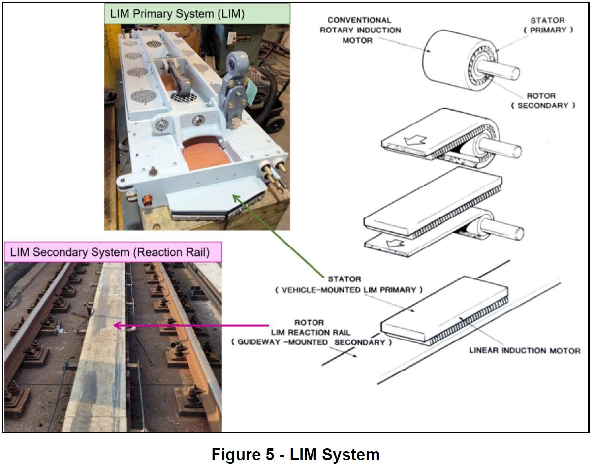
The Linear Induction Motor
A linear induction motor (or LIM) is a variation on a conventional rotary induction motor in which the field generated by the motor coil induces a magnetic field in the “rotor” (which is actually the fixed reaction rail on the track slab).
The difference between a rotary and a linear motor is that the structure is unrolled, and half of the motor is actually in the guideway (see diagram below). The coil on the train induces a field in the reaction rail and also pulls the train along the track using that field. Braking works the same way but in reverse with the car pushing against rather than pulling on the induced field in the rail.
Because the power is AC (alternating current), the field is constantly moving. In what might seem almost like magic, the motor operates by pulling itself toward, actually chasing, the ever moving induced field. This also depends on the frequency of the AC power so that the field moves at a rate the motor (and its load) can handle while coming up to speed. The variable pitched whine on the SRT cars as they start up is due to the change in the frequency of power fed to the motor and vibration of components in it.
In a rotary motor, clearances between the rotor (the part that turns) and stator are easy to control because the whole package is a single unit. With a LIM the two components are in separate places – one on the vehicle, and the other on the guideway. Although the nomenclature might seem odd, it is the reaction rail that is the “rotor” in a LIM because it moves relative to the car while the electric motor frame is stationary relative to the vehicle.
Efficient operation of the motor requires that the gap between the two components be as close as possible, but with a LIM, many factors can affect this spacing including:
- Dynamic movement of the car during operation including the effect of the weight of passengers on the car’s suspension
- Wheel wear affecting the height of the car above the “top of rail” line
- Track wear affecting the relative height of “top of rail” and the top of the reaction rail which are supposed to be the same (with minor tolerance as shown below)
- Movement of reaction rail components due to magnetic forces both vertically and in the direction of travel
- Integrity of the support structure holding the reaction rail in place on the guideway
A seasonal problem faced by Toronto (and occasionally Vancouver) is caused by snow accumulation. As a train passes, the reaction rail heats up melting snow which can then freeze as a layer of ice. This reduces the clearance between the face of the motor on the car and the top of the reaction rail plus its icy coating. There are similar problems with ice forming on the power rails from heating/freezing, compounded by the vertical arrangement of the SRT’s dual power rails. This is obviously not an issue in July. In a worst case situation, the line cannot operate because there is too much ice on the reaction and/or power rails.


Per TTC’s latest procedure [4], depicted in Figure 9, the LIM height with respect to the top of the running rails must be within 12.5 mm and 13.5 mm. This acceptable range is used during maintenance interventions at the carhouse to set the LIM height for all cars. Along with the reaction rail height tolerance (-1/+5 mm with respect to TOR), the resulting operational air gap range is between 7.5 mm and 14.5 mm.
Hatch LTK Report at p. 15
The height of the car-borne motor is adjustable in fine increments, and this is part of regular inspection of the SRT cars to maintain proper spacing. That is comparatively easy to do in the shop, but the vertical alignment of the reaction rail is quite another matter as it extends over the entire line. An ongoing concern is that an out-of-adjustment motor or reaction rail could hit each other, and scuff marks on the reaction rail show where this type of problem might be developing.
The motor includes protection in the form of a scraper to push minor obstructions on the reaction rail out of the way, and a skid bar just behind that. There is also a safety fender in front of the scraper (not shown below) that rides below the LIM height but above the reaction rail.

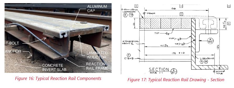
The reaction rail itself has two components. There is an aluminum cap (the part visible in the photo) and an iron inductor underneath. Where extra motor efficiency is needed, a laminated inductor is used, and that is the type of rail at the accident location just south of Ellesmere Station. The reaction rail itself is supported by a frame mounted on bolts set into the concrete guideway. Its vertical position is determined by nuts on either side of the feet of the frame.
Stability of those bolts is critical to prevent movement of the reaction rail. If the rail is not well anchored to the guideway, it can be pulled upward by magnetic forces from the car motors.
The reaction rail components – both the aluminum cap and the underlying support frame – are segmented. The segments are normally offset so that they do not align vertically, and each component reinforces the other’s resistance to movement under magnetic forces.
Both the integrity of the bolts and the cap-vs-inductor alignment would prove critical in the derailment.
(In the photo below, there are two pieces of black cable hanging alongside the reaction rail frame. This is the antenna of the train control system which has been cut here. This has nothing to do with the derailment.)
The Gannett Fleming Report
Gannett Fleming’s investigation included five components:
- Initial site inspection
- Detailed investigation work plan
- Concrete core sampling
- Metallurgical analysis
- Dynamic testing and incident re-enactment
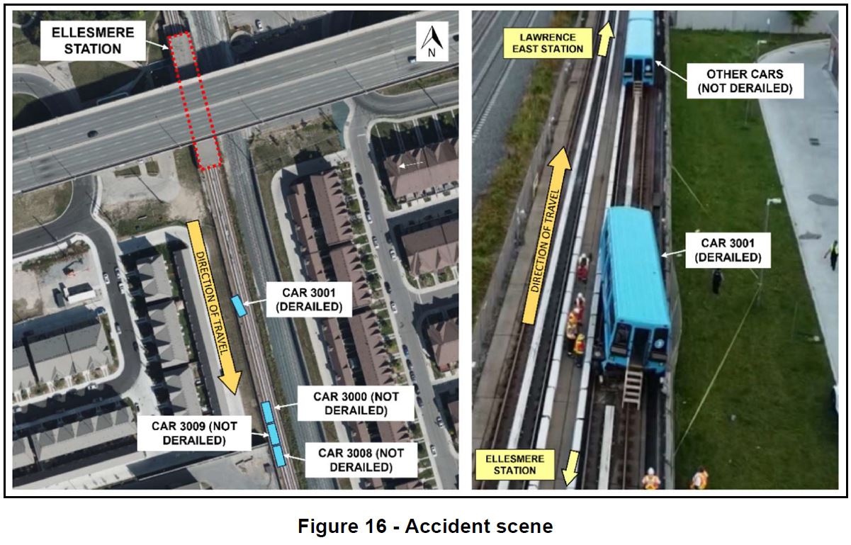
The initial investigation concentrated on a problem with the track and contact between the reaction rail and the car which lifted it off of the running rails. The impact drove one section of the reaction rail under another as shown in the photo on the right. (For more detailed photos, please see the report’s appendix).


July 24 was a warm day with a high of 26°C. On such days, the SRT operated at roughly half normal speed to avoid rail overheating through the combination of ambient temperature and heat from the induced motor current. This restriction was lifted at about 6:10pm.
Train 1 (run 61), the one preceding the derailment, was southbound at 6:37pm and its third car suffered minor damage from striking the reaction rail. Train 2 (run 63), at 6:43pm, was travelling at 40km/hr and its rear car struck the reaction rail causing the car to break away from the rest of the train and derail.


By the time Gannett Fleming arrived on the scene, the damaged car 3001 had been removed.
Their initial investigation showed that the running rails were within spec both for gauge (the distance between the rails) and cross-level (the relative height of the rails). There were “no concerns … observed” [p. 9] with the running rails nor with their mounts on the track slab. However, rub marks were visible on top of the reaction rail cap south from Ellesmere Station to the site, and they were present well before the event showing that alignment problems already existed. Furthermore, repairs on the reaction rail had left the joins in the cap and the underlying inductor at the same points rather than offset.
A similar issue was found 70m south of the derailment site, and the photo below shows how the gap in the reaction rail provides a location where a segment could move independently. These photos are clearly from two different locations.
A further problem was that “Many Tbolts (holding the aluminum cap to the induction plate frame on the reaction rail) were loose or missing.” [p. 16]


The bolts used to support the reaction rail frame were originally cast into the concrete slab, but maintenance over the years required that these were replaced. The photo on the left below shows a replacement bolt and the remains of an original bolt in the slab.
On the right is the replacement used for track maintenance. The Hilti anchor in Figure 21 has a sleeve at its base which expands into the new hole drilled into the concrete. The original bolts supplied by Hilti were replaced by the TTC with longer bolts that would protrude above the sleeve to support the reaction rail frame. This is a potential weak point because of forces on the bolts that can cause repeated bending stress.
The TTC’s design loads specify not only upward and downward forces, but lateral and longitudinal forces as the LIM pushes and pulls on the reaction rail. Every motor that passes over the rail (eight per train) produces stress in one or more directions.


The anchors at the derailment site were in various conditions following the incident as shown in the photos below (detailed comments keyed to the numbering are in the report). A variety of conditions were found including bolt fractures and deformation, sleeves not fixed in their mounting holes and bolts not attached to their sleeves.
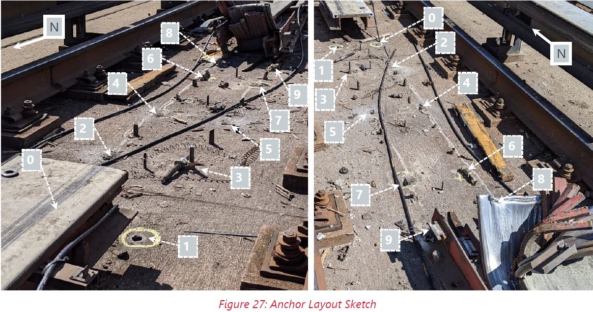
Two important issues noted by Gannett Fleming raise questions about the suitability of the replacement bolts and their installation.
Installation: No records of the anchor installation were provided, and it is not known whether the specified torque was applied to the nut during installation. The initial applied torque and pre-load in the rod could not be ascertained from the components retrieved from the site. The presence of drilling powder at the bottom of the hole indicates that the hole may not have been fully cleaned during installation. Furthermore, the TTC SOP requires that a torque seal be applied to the anchor bolt/nut, with a 6-month follow-up inspection to verify the torque seal condition (and thereby also verify that the nuts have not loosened). Torque seal was not found on the anchors and no records of follow-up torque inspection were provided.
Design: Although Hilti’s documentation states that this type of anchor is suitable for dynamic loading, it is unlikely that it was tested for the loading condition applied by the reaction rail. The torquing of the anchor induces a tensile pre-load in the rod between the cone and nut, and a corresponding clamping force between the nut/washer and the concrete. It is unlikely that the clamping force at this interface created enough frictional resistance to resist the applied horizontal loads, and therefore the connection would not be considered slip-critical. The height of the load application above the concrete surface (approximately 125 mm) increases the load at this interface by creating a lever effect. Once the frictional resistance is exceeded, a small slip would occur, and the anchor would continue to resist loads. However, over thousands of load cycles, the repeated slip between anchor components and concrete could result in loosening and/or unthreading of the anchor components.
Gannett Fleming Report at pp 20-21
A further issue was raised in the metallurgical report and echoed later by Systra Canada:
The report mentions several types of failure for the anchor bolts; fractured threaded rod and loose anchor, all of which were found on the system at different locations. A failure analysis of the fractured anchor bolts revealed that they failed due to cyclic loading, implying that they were already fractured prior to the accident. It seems that this failure mode was only found on newly replaced anchor bolt made from a combination of Hilti HSL-GR and a threaded stainless-steel rod. These bolts are used whenever a replacement of the anchor bolt is needed. The appendix E of the Gannett Fleming report details the analysis performed on a set of broken anchor bolt from the accident, original Hilti HSL-GR anchor bolt and a reference stainless-steel threaded rod. Although the mechanical properties of the stainless steel used for the threaded portion appeared to be similar to one another, the profile of the threads is different. The root of the thread is square on the threaded rod used by TTC whereas the Hilti is round. Such difference could have had an impact on the fatigue performance of the part and partly explains why the bolt fractured.
Systra Canada Report at p 10
At the repaired reaction rail segment south of the derailment site (shown in a photo above) there were similar issues, but with the structure intact and no room for debate about which problems pre-existed and which were caused by the force of the derailment.
Within one reaction rail segment which is supported by 10 anchors, the following was noted:
Gannett Fleming Report at p 21
- 2 anchors were fractured, with the fracture occurring directly below the lower nut of the reaction rail frame.
- 4 anchors were loose, and the rod could be moved within the hole.
- 3 anchors had loose nuts (the lower nut at surface of concrete is loose).
- 1 anchor appeared to be secure.
The pattern of damage on both the preceding train and the derailed one shows that the reaction rail was already loose and was striking passing cars. By the time the rear truck of 3001 arrived, the rail was high enough to snag the motor causing the train to break and the truck to be lifted clear of the running rails.
Vehicle maintenance records and condition showed that there were no issues with the state of the trains themselves. (See also the Hatch LTK Report which concentrates on the vehicles.)
Taking the available records at face value, there is no indication of vehicle maintenance-related defects leading to the derailment incident on July 24, 2023.
Gannett Fleming Report at p 22
Two appendices of this report deal with examination of concrete and metallurgical problems. In brief, the concrete cores taken from the site showed that the concrete was in good condition and would not have contributed to the anchor failures. The metallurgical review showed many issues with deformation and stress crack formation in bolts, but also showed that new bolts included defects (rust) that could be the site of future crack formation. I leave it to interested readers to read through the details.
The re-enactment testing was conducted at Lawrence East Station, and it involved successively loosening reaction rail bolts under a track section and recording the movement of the rail. This was not done at full service speed to avoid a repetition of the derailment, but to view how the rail responded to magnetic forces from the motor under different conditions.
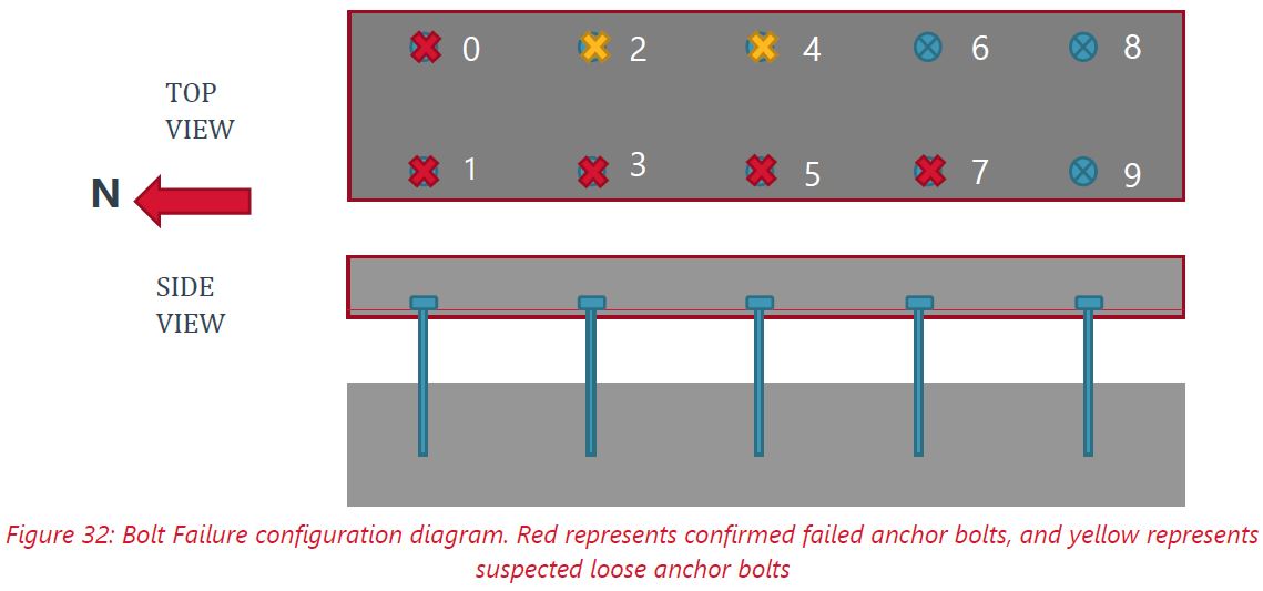
Upon careful review of the reenactment procedure’s video footage, a discernible conclusion emerges: the elevation of the reaction rail beyond the maximum permissible tolerances necessitated the failure of a minimum of two rows of bolts. This alignment corresponds with the structural insights garnered from the fractured bolts and failed anchors. Analysis of the structural components reveals that bolt/anchors 0, 1, and 3 exhibited signs of breakage and potential loosening preceding the incident. Scenario 7 indicated that a minimum of two rows of anchor bolts were required for the reaction rail to begin to bend upward and behave like a hinge; however, with only two rows of bolts failing, the reaction rail would not rise beyond tolerances as demonstrated in the videos.
Gannett Fleming Report at p 26
The actual failure pattern at the derailment site is shown in the diagram below. Both here and in the undamaged site discussed above, it is clear that the reaction rail had become almost completely detached from the concrete slab.
Gannett Fleming concludes that there were three potentially contributing factors to the derailment:
- Failure of anchor bolts
- Relative location of joints in the aluminum cap and laminated inductor
- Loose and missing T-bolts holding the cap onto the reaction rail
In their recommended actions, aside from thorough inspection and repair of all of the identified problems with the reaction rail structure, they cite the need for education so that maintenance crews will understand the behaviour of the system. That is a lesson that should apply to all aspects of TTC inspection and maintenance, not just to the now-closed SRT.
Education: In the instance of this derailment, the dynamics between the reaction rail and the LIM of the vehicle is a unique scenario in TTC’s network. Understanding the forces applied on the reaction rail, and the risks associated with the failure of the components would benefit inspectors.
Through integrated knowledge sharing between equipment and engineering teams, track inspectors gain the ability to discern high-risk failure points and critical locations that demand heightened vigilance. This informed approach enables timely interventions, targeted maintenance, and a proactive stance toward averting catastrophic failures. To implement this lesson, it is recommended to design training modules that encompass theoretical and practical aspects of train dynamics and foster continuous learning to adapt to evolving train technologies. Ultimately, this integration augments infrastructure assessment efficacy and fortifies overall network safety and dependability.
Gannett Fleming Report at p 31
The Hatch LTK Report
The Hatch LTK report deals mainly with a review of vehicle condition and maintenance records. It concludes that although some vehicles showed the effect of damage from striking or rubbing against the reaction rail, the problem lay entirely with the track, not the vehicles. The accident was not a derailment in the conventional sense, but a collision between the track and the guideway.
The report includes a discussion and diagrams of the Linear induction motor which I used earlier in the overview of that technology.
Cars on both the derailed train and the one that proceeded it suffered similar damage indicating this was likely from the same source.
One issue with the loose reaction rail (as described in the Gannett Fleming report above) is the effect of repeated stress as each of the eight motors of a train pass over the area and the potential for a cumulative effect. It was the rear truck of the last car that derailed.

The LIMs hang under each truck, and there is an adjustment that allows their position to be set in 0.5mm increments. Although the LIM itself is separate from the truck, the links are stiff and the relative movement of the motor to the wheels were considered “negligible” by Hatch LTK.
Inspections check the actual height at four points corresponding to the LIM suspension links to the car, as well as the condition of the assemblies from which they hang. The inspection interval of 30-36 days complies with the original manufacturer’s recommendation. The oldest inspection for any vehicle in the fleet was on June 20 (cars 3006 and 3007), and most were within July. (See Table 2, p 87.)
The SRT trucks use steerable axles so that the wheels turn into curves reducing forces on the wheel flanges and the tendency for wheels to climb over the running rails. This also reduces rail and wheel wear.
Hatch LTK found that the LIM heights on cars could not have caused the collision, and inspection of the fleet showed that this setting was close to spec for all cars. (See Table 3, p 88.) The combined effect of the range LIM and reaction rail height specs gives an acceptable air gap from 7.5 to 14.5mm.
There is a long section of the report detailing the car inspections and conditions found. Scratches were found on the face of several LIMs indicating that there had been contact with the reaction rail on an ongoing basis. This matches up with observations in track inspections that there were polished and scratched sections of reaction rail caps on the line.
There are many photos from the detailed inspection of the eight cars, and interested readers should browse the report for details. Here is a photo of the rear truck from car 3001 which was the one that struck the reaction rail and was lifted off of the track.

The Network Rail Consulting Report
The Network Rail Consulting report focuses on the protocols and record keeping for track inspection and defect maintenance on the SRT.
The line was supposed to be inspected every 72 hours by track patrollers during daylight hours. Defects are entered into the TTC’s MAXIMO database which creates work orders for defect removal.
Note: I have attempted to obtain all inspection and work orders for the SRT from June 1, 2023 onward, but await completion of an FOI request that is expected for mid-March 2024. So far, I have a small sample of inspection records from MAXIMO, but no work orders. It is worth noting that Network Rail clearly had the full set of inspection records going back years.
There is a training program for track inspection as well as a recertification process, although the latter has not been active recently. Originally this was computer based, but that system no longer exists and training is now all via paper documents. The five day course includes a discussion of the SRT including “a base degree of what the reaction rail is and also showcases its various components.” [p 2]
When defects are entered into MAXIMO they have various priority and colour codes. The table below is from the Systra Canada report.
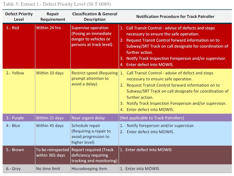
This scheme is derived from a previous work order system, MOWIS, and that is detailed in the Systra report later in this article.
Network Rail found that the inspection regime was followed based on a 9-week plan from the Senior Track Engineer. They noted that:
The patrollers did not report anything on that inspection [the one preceding the derailment] that they perceived to be a danger to trains. [p 4]
While the WAY111 training does review the SRT set up, it does not inform the patroller on what to inspect in relation to the reaction rail and the dangers with reaction rail defects. [p 5]
The Senior foreperson conducts a mandated mentoring for the patrollers … but this is more around the safety aspects of being track side rather than the quality of track inspection. [p 5]
It’s also evident that the track patrollers do not understand the impact of ‘combination defects’ in relation to the reaction rail, and although many defects are reported, they are reported separately, and the risk factor goes unrecognised. [p 6]
About half of the Track Patrollers have their certifications, and the others work as assistants under the mentorship of certified staff. Given that certification within one year of joining the group is a TTC mandate, this implies that there are many recent recruits to this section.
Reviewing the defect database, Network Rail found that there were:
- 139 reaction rail defects, of which
- 77 were “polished cap” defects
- These were almost evenly distributed across the line with 37 northbound and 40 southbound
- 28 were “missing/loose T bolt defects
- 77 were “polished cap” defects
The report includes two tables listing these defects going back to 2016 for polished cap, and to 2013 for missing T bolts.
There were only five new defects reported in 2023. Over 2022-23 there have been seven restricted speed zones (RSZs) logged, one of which was a duplicate entry and is noted as such. None of them is at the location of the derailment, chainage 13+510, about 60m south of Ellesmere Station southbound.
The detailed lists include a missing T bolt report for this location in May 2021, but more critically a “Reaction Rail Polished Top Cap Raised 1/2 inch on the approach end”. The date is July 9, 2023, two weeks before the derailment.
Although the priority level is not shown in the Network Rail report, this item does appear in the preliminary FOI extract I received on January 17, 2024. The priority assigned to this defect is “4” which is the lowest priority available.

A separate test of the reaction rail is a “Top High Spot Test” measuring the relative height of the reaction and running rails. This is performed quarterly by the Vehicles Department and sent to Maintenance Engineering. There were no reported faults from November 2022 onward. An important point here is that if the test does not review the reaction rail under load with the magnetic attraction of a LIM motor, the ability of the rail to shift upward would not be caught by this test.
Network Rail’s recommendations cover many aspects of track inspection, reporting and maintenance. These apply to all TTC tracks, not just to the SRT. They include:
- Revised training including both computer based graphics and field training.
- Ensuring that personnel are not fast-tracked into patroller roles.
- The risk of “combination defects” where two or more problems at the same location could combine to increase risk, and should be treated as one flaw increasing their priority and possibly requiring a restricted speed zone.
- Establishing a requirement for positions above track patroller up to engineering participate in inspections so that they “understand the state of the system” [p 13].
- A revised code structure for defects, and the ability for more senior staff to prioritize defects for repair based on their knowledge and experience.
- Ensuring timely planning for defects and close-out of completed work to avoid clutter in the list of active problems.
- Improve track standards including explanations of how out-of-spec conditions are to be handled and what the response to defects should be. This would also allow auditing against a defined process.
- With respect to SRT re-opening which did not occur:
- Defects located by Gannett Fleming to be repaired.
- Re-brief to patrollers on the reaction rail before resuming inspections.
- Operate the SRT at 25km/hr with an experienced engineer riding in the front car of trains.
- Paint the top cap white to make identification of strikes with the LIM face obvious and perform immediate maintenance to resolve these.
It is clear that the reaction rail and its components was the primary cause of the derailment, data shows that the track patrollers were identifying reaction rail defects and taking safety precautions were they deemed necessary.
The omission of detailed standards for SRT reaction rail and its exceedance limits lead to a degree of uncertainty on how to maintain the reaction rail defects.
Asset data management required more stringent management to control the quality of data held within the MAXIMO data base, to recognise and remove more onerous defects the above recommendations will assist in that.
Reducing the reliance on the track patrollers by installing a hierarchy of track inspection will greatly improve the knowledge of track condition.
Network Rail Report at p 16
The Systra Canada Report
The Systra Canada report was prepared for the TTC Safety Department as a review of the three previous reports as well as the drop in defect reporting for reaction rails by a factor of more than 8 over 2022-23 compared with 2018-21.
Systra rehashes some of the material from earlier reports and I will not repeat their analysis here.
In their review of the TTC organization, they noted that communication between three groups responsible was uneven, and by implication this could impede maintenance planning and work.
The drop in the reported defect count was associated with a move from the old MOWIS system to MAXIMO, but that migration was not well documented. The larger concern is that when the SRT shutdown was originally announced for November 2022, some defects were no longer reported because their time-to-repair would be beyond the shutdown date. Another problem was that issues with integrity of anchor bolts were difficult to spot because they are under the reaction rail, although that concern has existed since the line opened.
Systra charts the rate of defect reports in recent years.


Systra noted that there were two systems for measuring reaction rail height, but they were performed by different departments with different goals. One using a laser is performed by Rail Cars and Shops (RC&S). The other using visual inspection is by the track patrollers.
The laser device is installed near the LIM towards the center of the [test] car. This test is conducted by RC&S every 2-3 months but did not have a clear requirement for periodicity since it was only justified by the quantity of damages found on the LIM.
The investigation videos from Gannett Fleming’s show as the LIM passes over a section of reaction rail, the magnetic lifting force stops near the edge of the LIM and the reaction rail would immediately fall to its original position. Unfortunately, this test was not conducted with the laser measuring equipment to determine whether it was able to detect a loose reaction rail. It could be assumed that mounting the laser sensor between the LIM and the reaction rail could have enabled the detection of loose reaction rail section, but such mounting solution is not possible given the available space. Also, the magnetic forces generated by the LIM are varying depending on the phase the car is going through (acceleration braking or coasting). All these factors make it difficult to conclude if this inspection could have detected a loose reaction rail.
In addition, RC&S explains that the SRT Laser Inspection was started approximately ten years ago and was intended to supplement regular reaction rail height inspections performed by Track and Structure, and not to supersede them. According to the Track and Structure department the measurement of reaction rail height is only performed by the SRT Laser Inspection Train, the track patrol inspection is only visual without tools. This demonstrates that there is a clear misunderstanding between these two departments regarding the expected robustness of that procedure.
Systra Report at p 16
With the impending closure of the line, only preventative maintenance was performed on the reaction rail and this was subject to what the track patrol would detect.
Systra observes that the new Hilti bolts used on the SRT since 2016 brought problems.
The new anchor design uses a Hilti HSL-GR anchor bolt where the main bolt is discarded by TTC and replaced by a longer stainless-steel threaded rod. The longer stainless-steel threaded rod allows the mounting of the reaction rail to be at the correct height. The Hilti HSL-GR uses an expansion sleeve to maintain the assembly in place. This type of anchor is normally used to clamp down a thick metal plate where Hilti offers wide range of available fixture thickness to accommodate the installation. For the application on the SRT Line 3, the anchor is used without the fixture thickness and is tightened directly onto the concrete slab which is not how this anchor is intended to be used according to the manufacturer. No engineering reports were made available to SYSTRA to evaluate if this anchor solution is suitable for this application. The Gannett Fleming’s report mentions a vertical pull test to ensure sufficient anchor strength in the vertical direction, but no test in the horizontal direction or fatigue assessment of this anchor in this application was conducted.
Using the Hilti HSL-GR with a long threaded stainless-steel rod to support the reaction rail of the SRT Line 3 can explain why several were found by Gannett Fleming to be fractured, see section 7.3. These anchors are not intended to be used in bending load as it is the case on the SRT Line 3. The metallurgical analysis confirmed that this fracture was due to cyclic loading, hence failed in fatigue probably over a long period. Combining this with the inspection process of the track patroller of walking over the reaction rail during revenue service hours suggest that this failure was not systematically reported due to its difficulty to detect. It is possible that the condition of these new anchor bolts became worse over the last few years and was not detected by the track patroller given their inspection method. It is important to note that this new anchor design was progressively replacing the original anchor design over the last 7 years.
Systra Report at p 18
On top of these issue are questions raised by Gannett Fleming about improper installation of the new bolts.
Among Systra’s conclusions and recommendations are:
- The number of defects before 2022 might have been artificially high due to duplicates in a former work order system, MOWIS, that were migrated into MAXIMO. However, Systra offers no guidance about whether this was actually the case.
- The new anchor bolt design is problematic as discussed in the Gannett Fleming report.
- The anchor bolts were never subject to preventative maintenance.
- Some preventative maintenance was not carried out once the line’s closing was announced.
- Top cap painting was discontinued making it difficult for track patrollers to identify new areas of “polished cap” that would indicate a clearance problem.
- Training and experience of track patrollers is problematic with many staff in this group relatively recently and many not yet certified.
- There are no standard criteria for priority levels of defects, nor for combinations of defects.
Much of this applies to the SRT environment, but it is hard to believe that practices there are not common with the larger subway system considering that the same track patrollers work on all lines.

Steve, you’re doing a great public service. Always interested to read your emails and analysis. Thank you.
LikeLiked by 3 people
Consultant Report – Hatch LTK, Scarborough Rapid Transit (SRT) Vehicle Accident Investigation Report
Dated September 28, 2003 ***SHOULD BE 2023***
Steve: Fixed. Thanks.
LikeLike
The same people in charge who forgot about the busway’s environmental assessment, forgot about the SRT derailment reports?
LikeLike
All these consultants reports just show the TTC has no internal staff for self assessment. That alone is disturbing.
Steve: This is a case where outside eyes were needed, but the problems with existing internal practices and standards is very troubling.
LikeLiked by 1 person
Fascinating stuff Steve! Did you have an engineer help you by chance?!! 😉
Steve: No. It is all my own work, but I have hung around engineering types long enough for some of that to rub off.
I’m enjoying reading it thought I may have to wait til later to finish. But shit. It sure sounds like a whole lot of not caring not paying attention and wow. Staff not trained.
Although Hilti’s documentation states that this type of anchor is suitable for dynamic loading, it is unlikely that it was tested for the loading condition applied by the reaction rail. The torquing of the anchor induces a tensile pre-load in the rod between the cone and nut, and a corresponding clamping force between the nut/washer and the concrete.
Wow. Impressive. Impressive report and impressive that the situation was a lack of maintenance and lack of paying attention, plus incorrect bolts, etc. At a glance. Egads. And yes, same people inspect everything? Clearly a not giving a shit attitude prevails at some level or all levels.
LikeLike
Let’s discuss without mincing words: The failing mounting “system” for the reaction rail was at best, a poor 1st year engineering student prototype. No engineer I know would even propose such a “system”, let alone deploy it.
We shouldn’t cast blame on TTC maintenance or inspection (albeit, I can’t fathom why anyone would decide to stop the TTC’s practice of applying white paint to the aluminum reaction rail top portions after repairs to make it easier to quickly spot reoccurring failed mounts). But instead, let’s put ourselves in their shoes: Just imagine how tricky it would be to ensure that all the absurdly tall position adjustment bolts were equally supporting the reaction rail – this design should never have made it past an early prototype stage because by simply adjusting one nut, some of the other bolts are guaranteed to be pulling up or down against each other and their concrete foundations. And somehow ensuring that they all work in unison is going to require stress gauges miraculously installed on each bolt as the nuts are adjusted to level the reaction rail – unbelievably bad engineering. The mounting “system” **absolutely guarantees** uneven stress on each bolt before the first train accelerates or decelerates above – thus the bolt failure was baked-in from the outset. (It’s surprising how long the original bolts lasted with the varying direction and amplitude of additional torque applied with each passing train.)
Steve: The original bolts were cast into the foundation, and so would not have had the problem of torque stress. The reason for a new design is that by the mid 2010s, they were starting to fail and a new design was needed that could be installed in the existing track slab.
Since the height of the reaction rail is ALWAYS relative to the main rails on which the wheels run, it would logically be mounted integral to such main rails by attaching it to a series of cross-bars bolted directly to such main rail at the main rail’s anchor points to the concrete – not ever supported mid-air from the concrete by threaded tall bolts which obviously (assuming some method of ensuring these tall bolts were all working together) would be subject to a relatively large moment. Apparently, the concrete is in good shape, as are the main rails – so why isn’t the obvious straightforward solution put in place??
Toronto is in no financial condition to scrap the Scarborough SRT for a problem which is as simple to repair as remounting the reaction rail correctly. In fact, one could likely argue that this issue is far more readily, and affordably corrected than the multitude of serious issues with the leaking Crosstown tunnels and other recent project setbacks.
Toronto also has made a sustainability commitment to our planet – and specifically, in this case, the city cannot meet sustainability claims unless it repairs and reuses, instead of jumping to replace with new consumption. Linear induction systems like the Scarborough SRT have a larger up-front materials impact, but offer long, reliable lifespans. The failure of an extremely poor reaction rail mounting system should not condemn the entire transit line.
With current GTHA LRT’s typically consuming 125 million kgs of concrete in their initial construction, and then frequently requiring tearing up and replacement of such concrete to service rails such as the recent Broadview and upcoming St. Clair track ‘renewal’ also requiring extremely long periods of diesel buses while LRT’s sit unused, we must finally look closely at the environmental damage of each decision – especially decisions not to repair and reuse what we have. Assuming the reports are correct, and the Scarborough SRT concrete is in good shape – lets sustainably use it and the stations for years to come. Simply fix the reaction rail mounting with a good design and enjoy the benefits of induction for years to come.
Steve: With the decision to build a subway in Scarborough, the idea of using/reusing the SRT infrastructure is a non-starter. This technology had more problems baked in from the original design than the reaction rail mount including its likelihood of failure in snowy or icy conditions, and its inability to tolerate a high ambient heat, although I must say that 26C is hardly toasty by Toronto standards.
LikeLike
Lax maintenance on the streetcar OCS. Lax maintenance on the SRT. Fresh outside consultants are snooping around on the subway system. Where’s Rick Leary in all of this? Quietly collecting pay cheques in the background.
LikeLiked by 1 person
Thank you Steve for this summary, it’s very illuminating.
As usual, such accidents are multi-determined. What never stops being painful though is learning just how easily and cheaply they are avoided. I’m quite surprised to learn that they stopped painting the reaction rail. I thought it was painted the last time I rode the line about 2017.
Let’s hope that procedures will change as a result in Toronto. And that Vancouver reads the reports in full.
LikeLiked by 1 person
The same guys who “forget” to do an environmental study when it is clearly required.
The TTC has always sabotaged the RT since it’s birth…
LikeLike
Steve, thank you for the time you put in and the areas of deficiences you have highlighted in how TTC has failed in the maintenance and upkeep of the RT. I am not sure how much of the taxpayers money has been spent in commissioning these consultant studies. As you rightly pointed out, it is more than troubling to see the lack of any follow up or plan on the part of TTC to address these issues. I would think this is an appropriate case for the Toronto Auditor General office to be called in to find out what’s amiss.
LikeLike
The motor has been contacting the reaction rail even before the accident? Is that why when the train arrives, we hear lots of clanging metal on metal instead of that sweet inverter noise?
Steve: Could be.
LikeLiked by 1 person
Steve – Thank you for endless work and the time you put into keeping us all informed and up to date on the TTC.
For the SRT, I am very troubled over the lack of accountability on the maintenance issues found. This was an accident waiting to happen and it could have been a lot worse, image a full train during peak rush hour outside of summer.
I am also very bothered over the “double-speak” from TTC regarding the initial shut down plans for the SRT. The main reason for the shutdown in June 2023 and for years before that were the vehicles: “the trains in service are 10 years past their design life.” – CP24 Published Thursday, June 22, 2023 12:10PM EDT.
But after the shutdown and the derailment, the vehicles are described as in good shape to be sold to Detroit: In an interview with CP24 on Tuesday, TTC spokesperson Stuart Green said “with a bit of work,” Detroit could get another five or 10 years of life out of the equipment, which is “cheaper than purchasing new trains.” CP24 Published Dec. 19, 2023 9:21 a.m. EST.
So are the trains good or not? Would it have cost more money to fix the trains than to build the busway – I would think not as Detroit is not the most well funded transit system to spend 40- 60 million to upgrade the trains.
This really begs the question, why don’t we just fix the trains as per Detroit’s plan, fix the track (since we have the defects from the consultants) and run the SRT for 10 years until the SSE is done. This would be cheaper than the busway and operating the buses.
The LIM technology was the wrong choice but we will lose a generation of transit users with this SRT shut down. The only saving grace is with fare integration soon, if people can time their travels, they can the Stouffville GO line downtown and back soon without paying twice.
Steve: First off, Detroit’s service and demand are nowhere near the SRT’s level, and we were already short trains to provide adequate service as demand builds back post-pandemic. Our trains are “pushed” a lot harder than theirs. Given the issues revealed by the technical reports, nothing short of a complete rebuild of the reaction rail and supports over the entire line would convince me that it is safe, and I suspect the TTC knew that and would not take the risk.
LikeLike
There are LIM proponents occasionally popping up to point out new LIM technology installations in China, Paris, etc. I wonder what technical merits led to these decisions?
Alternately, of course, it could just be a very effective sales job.
LikeLike
Why is it that this and other TTC rail incidents are not investigated by the (federal) Transportation Safety Board (TSB)? Just because the TTC isn’t federally regulated? Surely if a GO train derails, even on Metrolinx track, the TSB would be on the job, because it’s – you know – a train. Same for Ottawa’s O-Train, non? KW and Mississauga/Brampton LRTs? Who or what draws the line?
Related, what was the cost of this entire investigation, that presumably the TTC had to pay for? Could the TTC somehow “opt in” to TSB investigations? TSB certainly has the expertise and the ability to contract out specialized stuff as appropriate, and it would surely be a lot cheaper if the feds are paying!
Steve: The cost of these reports has not been published. It is quite likely within the spending limit that the CEO does not have to bring this to the Board for approval.
LikeLiked by 1 person
Good analysis of how the TTC got to the LRT accident. Two points stand out:
Steve: Yes, there were inherent design flaws coupled with poor training for inspection and maintenance.
And the only other point I will make in addition here is that the SRT was NOT an LRT. It is a mini-metro, or some such, but it was “LRT” only as a marketing ploy by the Ontario Government.
LikeLike